 |
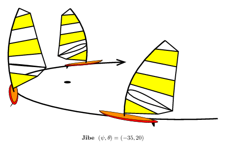
\input fig4tex %-------------- % Definition of macros %-------------- \def\board{% Draws the board % Main points \figpttra 1:=0/0.22,13/ \figpttra 2:=0/0.3,11/\figpttra 3:=0/2.7,11/\figpttra 4:=0/2.7,11/ \figpttra 2:=2/0.5,12/\figpttra 3:=3/0.3,12/ \figpttra 5:=0/0.3,11/\figpttra 6:=0/2.5,11/\figpttra 7:=0/2.5,11/ \figpttra 5:=5/0.4,12/\figpttra 6:=6/0.2,12/ \figpttra 5:=5/0.07,13/\figpttra 6:=6/0.06,13/\figpttra 7:=7/0.04,13/ % Bottom point of the mast \figptBezier 8::0.45[1,5,6,7]\figptorthoprojplane 8:=8/1,12/ % Define the fin and draw it \figpttra 20:=4/-0.30,11/\figpttra 21:=4/-0.25,11/ \figpttra 22:=4/-0.05,11/\figpttra 23:=4/-0.15,11/ \figpttra 21:=21/-0.15,13/\figpttra 22:=22/-0.5,13/ \figset(fillmode=yes,color=\Blackrgb)\figdrawBezier 1[20,21,22,23] % Compute the symmetric part of the board and draw it \figptssym 20=2,3/1,12/ \figset(width=default,color=\Redrgb)\figdrawBezier 2[1,2,3,4,21,20,1] \figset(fillmode=no,color=\Blackrgb)\figdrawBezier 2[1,2,3,4,21,20,1] \figptssym 20=5,6/1,12/ \figset(fillmode=yes,color=\DarkOrangergb)\figdrawBezier 2[1,5,6,7,21,20,1] \figset(fillmode=no,color=\Blackrgb)\figdrawBezier 2[1,5,6,7,21,20,1]} %-------------- \def\sail{% Draws the rigging set % Mast \figpttra 21:=8/1.5,13/\figpttra 22:=8/3,13/\figpttra 23:=8/4.5,13/ \figpttra 21:=21/-0.6,11/\figpttra 22:=22/-0.6,11/ % Sail \figptBezier 40::0.04[8,21,22,23] \figptBezier 31::0.230[8,21,22,23]\figpttra 41:=31/1.56,11/\figptrot41:=41/31,2,12/ \figptBezier 32::0.333[8,21,22,23]\figpttra 42:=32/2.08,11/\figptrot42:=42/32,0,12/ \figptBezier 33::0.423[8,21,22,23]\figpttra 43:=33/1.85,11/\figptrot43:=43/33,-10,12/ \figptBezier 34::0.576[8,21,22,23]\figpttra 44:=34/1.58,11/\figptrot44:=44/34,-15,12/ \figptBezier 35::0.736[8,21,22,23]\figpttra 45:=35/1.25,11/\figptrot45:=45/35,-15,12/ \figptBezier 36::0.888[8,21,22,23]\figpttra 46:=36/0.85,11/\figptrot46:=46/36,-20,12/ % Wishbone \figpttra 37:=32/0.2,11/\figpttra 38:=32/1.6,11/ \figpttra 37:=37/0.5,12/\figpttra 38:=38/0.05,12/ % Draw the sail \figset(fillmode=yes,color=\Yellowrgb) \figdrawline[40,31,41]\figdrawline[33,34,44,43]\figdrawline[35,36,46,45] \figset(fillmode=no,width=1.5,color=\Blackrgb) \figdrawline[31,41]\figdrawline[33,43]\figdrawline[34,44]\figdrawline[35,45]\figdrawline[36,46] \figdrawline[40,41,42,43,44,45,46,23] % Draw the wishbone \figdrawBezier 1[32,37,38,42]\figptssym 37=37,38/8,12/\figdrawBezier 1[32,37,38,42] % Draw the mast \figset(width=2)\figdrawBezier 1[8,21,22,23]} %-------------- \def\funboard{\boardposition\board\sailposition\sail} %-------------- \def\axes{% Defines the local axes linked to the board \figptBezier 0:$P$:\abscissa[15,16,17,18] \figvectDBezier 21:1,\abscissa[15,16,17,18]\figvectU 21[21]\figpttra 1:=0/-1,21/ \figvectP 11[0,1]\figvectC 13(0,0,1)\figptrot 2:=1/0,90,13/\figvectP 12[0,2]} %-------------- \def\jibe{% Draws the funboard at 3 successive positions % First position \def\boardposition{\def\abscissa{0.2}\axes} \def\sailposition{\figpt 20:(0,0)\figptrot 11:=11/20,20,12/\figptrot 13:=13/20,20,12/ \figptsrot 12=12,13/20,20,11/} \funboard % Second position \def\boardposition{\def\abscissa{0.55}\axes\figpt20:(0,0)\figptsrot12=12,13/20,-40,11/} \def\sailposition{\figpt 20:(0,0)\figptsrot 11=11,12/20,70,13/ \figptrot 11:=11/20,-35,12/\figptrot 13:=13/20,-35,12/} \funboard % Third position \def\boardposition{\def\abscissa{0.95}\axes} \def\sailposition{\figpt 20:(0,0)\figptrot 11:=11/20,20,12/\figptrot 13:=13/20,20,12/ \figptsrot 12=12,13/20,-20,11/} \funboard} %-------------- \def\trajectory{% Draws the trajectory and the floating mark \figset(width=2)\figset arrowhead(length=0.6)\figdrawarrowBezier [15,16,17,18] \figpttraC 1:=19/1,0,0/\figpttraC 2:=19/0,1,0/ \figset(fillmode=yes,color=\Blackrgb)\figdrawcirc 19,1,2(0.2)} %-------------- \def\newfig{% Creates a new graphical file and a new figure % 2. Creation of the graphical file \figdrawbegin{} \trajectory\jibe \figdrawend % 3. Writing text on the figure \figvisu{\figBoxA}{{\bf Jibe}\ \ $(\psi, \theta)=(\Valpsi, \Valtheta)$}{} \vskip1.5cm \centerline{\box\figBoxA} } %-------------- % Program %-------------- \figinit{cm, realistic} % 1. Trajectory control points \figpt 15:(7,3)\figpt 16:(2,-6)\figpt 17:(-8,-5)\figpt 18:(-2,6) % Floating mark position \figptcurvcenter 19::0.5[15,16,17,18] % First figure \figset proj(targetpt=19, distance=20) \def\Valpsi{-35}\def\Valtheta{20}\figset proj(psi=\Valpsi, theta=\Valtheta) \newfig % Second figure \def\Valtheta{90}\figset proj(theta=\Valtheta, distance=50) %\newfig \bye |